MD0 Mod Екн2: Difference between revisions
SnakeTuning (talk | contribs) No edit summary Tag: wikieditor |
SnakeTuning (talk | contribs) No edit summary Tag: wikieditor |
||
| (One intermediate revision by the same user not shown) | |||
| Line 8: | Line 8: | ||
To process these high-voltage signals and converting them into digital output in the Honda ECU installed a daughter-board, also known as [[VR Conditioner]] (see Fig. 2). The distinctive feature of this [[VR Conditioner]] is its adaptive sensitivity reduction to the input voltage from the [[VR_SENSOR|VR Sensors]] as the engine RPM increases. | To process these high-voltage signals and converting them into digital output in the Honda ECU installed a daughter-board, also known as [[VR Conditioner]] (see Fig. 2). The distinctive feature of this [[VR Conditioner]] is its adaptive sensitivity reduction to the input voltage from the [[VR_SENSOR|VR Sensors]] as the engine RPM increases. | ||
This is a logical approach for handling [[VR_SENSOR|VR Sensors]] as the input voltage can change significantly. However, this poses a significant problem when emulating OEM distributor Signals. The accuracy and correctness of ignition | This is a logical approach for handling [[VR_SENSOR|VR Sensors]] as the input voltage can change significantly. However, this poses a significant problem when emulating OEM distributor Signals. The accuracy and correctness of ignition are highly sensitive to the input voltage at the ECU. If the voltage is not correct at current RPM, Ignition timing begins to "drift" and later "missfire". | ||
[[File:VR_Signal_Conditioning.jpg|right|thumb|Fig. 3. Correct output vs "Drifting" Ignition comparison]] | [[File:VR_Signal_Conditioning.jpg|right|thumb|Fig. 3. Correct output vs "Drifting" Ignition comparison]] | ||
| Line 17: | Line 17: | ||
After a detailed researching of the [[VR Conditioner]]'s operation, we found a simpler and more effective Distributor Removal Solution (Patent pending). It's proposed "turn off" the adaptiveness of the [[VR Conditioner]], which would allow ECU to consistently work with low-voltage signals. | After a detailed researching of the [[VR Conditioner]]'s operation, we found a simpler and more effective Distributor Removal Solution (Patent pending). It's proposed "turn off" the adaptiveness of the [[VR Conditioner]], which would allow ECU to consistently work with low-voltage signals. | ||
Applying this simple modification allow us to generate stable trigger patterns up to 14000 RPM with 0.1 degree Ignition tolerance | Applying this simple modification allow us to generate stable trigger patterns up to 14000 RPM with 0.1 degree Ignition tolerance. | ||
Latest revision as of 17:03, 31 May 2024
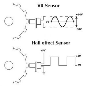
In the distributors of Honda B, D, F, and H Series engines, there are three Variable Reluctance Sensors: CKP, TDC, and CYP. The voltage across these sensors varies with the engine's RPM, ranging from approximately ±5V to ±60V.
VR Sensors is critical for the ECU to maintain correct engine angle tracking. Unlike modern Hall sensors, which provide a digital output, VR Sensors produce an analog signal whose amplitude varies with the speed of the engine (see Fig. 1). This variability can lead to signal integrity issues at high RPMs, where precision is critical for efficient engine performance.

To process these high-voltage signals and converting them into digital output in the Honda ECU installed a daughter-board, also known as VR Conditioner (see Fig. 2). The distinctive feature of this VR Conditioner is its adaptive sensitivity reduction to the input voltage from the VR Sensors as the engine RPM increases.
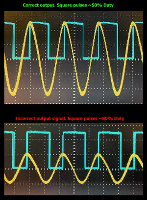
This is a logical approach for handling VR Sensors as the input voltage can change significantly. However, this poses a significant problem when emulating OEM distributor Signals. The accuracy and correctness of ignition are highly sensitive to the input voltage at the ECU. If the voltage is not correct at current RPM, Ignition timing begins to "drift" and later "missfire".
Waveforms are illustrate two scenarios: Correct output at 8000 RPM vs Reduced voltage output (see Fig. 3). The blue trace shows the output from the VR Conditioner, and the yellow trace is the input from the VR Sensor. This visualization helps in understanding the need for stable input voltage for accurate ignition timing.
To emulate Distributor, one might consider designing an electronic device to mimic the function of VR Sensors. However, the characteristics of VR Sensors and the necessity of double signal converting from digital to high-voltage and back can severely impact the accuracy of ignition timing at high RPMs. Additionally, high-voltage emulation would not be compatible with Standalone ECUs without additional signal converters.
After a detailed researching of the VR Conditioner's operation, we found a simpler and more effective Distributor Removal Solution (Patent pending). It's proposed "turn off" the adaptiveness of the VR Conditioner, which would allow ECU to consistently work with low-voltage signals.
Applying this simple modification allow us to generate stable trigger patterns up to 14000 RPM with 0.1 degree Ignition tolerance.

